FPGA bluetooth communication technology Android mobile phone based intelligent electronic lock control system
 2021-12-10 11:08

With the continuous improvement of people's security awareness and the continuous development of intelligent technology, in response to user demand for intelligent electronic locks with high safety factors, FPGA Bluetooth communication technology is used to design a system electronic lock based on FPGA Bluetooth communication technology. . The electronic lock is directly controlled through the APP of the mobile phone, and the electronic lock has double encryption. It has the functions of unlocking and modifying the password, the administrator controls the user unlock information table and adding and deleting user information that can be unlocked. After testing, the system is easy to use, dynamic and flexible, safe and reliable.
1.1 Architecture of the intelligent electronic locking system
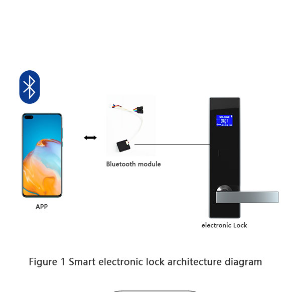
The smart electronic locking system uses a Bluetooth 4.0-compliant mobile phone to establish a connection with the Bluetooth module on the FPGA board, send commands through the mobile APP, and complete the data transmission with the Bluetooth module through sending and serial port reception. modules. Simple serial port commands are analyzed, identified, judged and executed through the command analysis module and command response module, and then the on and off of the relay connected to the FPGA board is controlled to perform the function of electronic lock switch. After FPGA receives the serial port data transmitted by the Bluetooth module, it will send the corresponding data and command response to the mobile phone APP through the Bluetooth module. In this process, FIFO is used to store the data to be sent. The architecture of the intelligent electronic locking system is shown in Figure 1.
1.2 Smart electronic lock design
If this smart electronic lock is applied to an office, lock A is the office door and lock 1, lock 2 and lock 3 are the lockers of user 1, user 2 and user 3. If the phone number User entered mobile exists in the system, the office door is opened, and then the password is entered. If the username and password match a particular locker, the locker is opened, as shown in Figure 2. The user password information for the system's electronic lock is stored in a pivot table, as shown in Figure 2. Table 1 (Initialized User Password Information Table). This table will be updated in real time as the administrator adds users, removes users, and member administrators modify passwords.
2.1 Bluetooth module
Bluetooth wireless technology is one of the most widely used global short-range wireless standards. The system bluetooth module is a bluetooth 4.0 module based on TI's CC2541 chip, which has a configuration space of 256 KB and follows the Bluetooth V4.0 BLE specification. The factory default setting of the Bluetooth module in this system is to communicate with the FPGA through the serial port protocol and process the sent and received data according to the UART serial port communication protocol.
The UART serial port protocol is to transmit each character of the transmitted data bit by bit. The UART data frame format is 1 start bit, 5 ~ 8 data bits, 1 bit of parity or no parity, and stop bit 1, 1.5 or 2 bits. The UART data frame format is shown as in Fig. 3. To speed up the development process, the system does not set the parity bit. The frame format adopted is 1 start bit, 8 data bits, no parity bit and 1 stop bit [5].
3-function test of the intelligent electronic locking system
The functional realization of the intelligent electronic locking system based on FPGA Bluetooth communication technology, the testing process is as follows:
(1) Install the BLE Bluetooth serial terminal APP, turn on the mobile phone's Bluetooth, and connect and pair with the Bluetooth module on the FPGA board.
(2) Enter the corresponding commands in the APP to complete the four unlock functions, add user information, delete user information, and modify user passwords.
(3) As shown in Figure 4, the mobile phone number of the incoming user exists in the system and the door lock of office A is open (all LEDs are on); if the password is correct, the locker is 1 open (the digital tube shows 00000001).
Observations: * Wxxxxxxxx: enter phone number (unlock), * Nxxxx: enter password (unlock), * Rxxxx: enter new password (modify user password), * Sxxxx: enter phone number (add user information), * Pxxxx: enter password (Add user information), * Gxxxxxxxx: Enter phone number (delete user information).
4. Conclusion
This system is a smart electronic lock control system based on Android mobile phones. FPGA receives data from the information entered in the APP of the mobile phone. This data is used as double-encrypted data to control the opening of the electronic lock. It has high security, strong encryption, and good flexibility. And this system has diversified and dynamic functions, Starting from the office door lock opening, different users can open different locker locks and have a private space in the public environment. Not only can new users be assigned to empty lockers, but user information can also be deleted to free the lockers for others to use. Users can modify lockers unlock password and update lockers occupancy and unlock conditions under actual conditions. hour.